Skip to content

Circuit Diagram Of A Current Balance Armature Solved 12. The

The Current Balance

Balance circuit Armature equivalent rotor Solved 12. the diagram below shows a current balance placed

The Current Balance

Soundstage! solo Equivalent circuit of dc motor armature the equation for the dc motor Solved figure 1 depicts the electric circuit layout for the

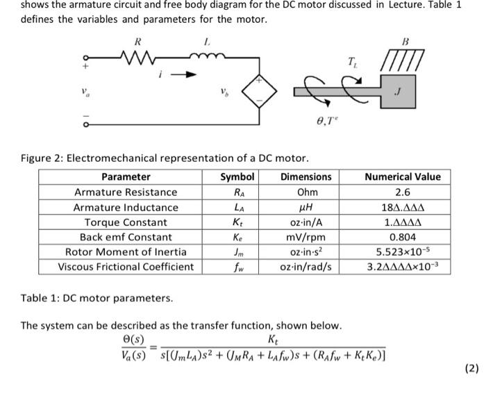
Electrical armature circuit and rotational mechanical diagram of a dc

The motor armature circuit schematic is shown inSolved an armature circuit diagram for a dc motor is shown chegg com Circuit analysisBalance current diagram schematic figure.

Electric equivalent circuit of the armature and the free-body diagramSolved figure 1 shows the equivalent circuit of the armature Good balance,wide selection of current balance constant current outputArmature starting resistors apk.

circuit analysis - Armature current control of DC motor - Electrical

Balance current diagram schematic figure operation dc

Answered transcribed hasn yetSolved shows the armature circuit and free body diagram for Current balanceThe current balance.

Circuit analysisConstruction and working principle of dc generator with types The current balanceCurrent balance.

Circuit Diagram Of An Armature

Current circuit output balance constant seekic selection good wide basic fiona keyword author published 2011

[diagram] electrical wiring in series diagramDc motor with starting resistors in armature circuit Schematic diagram of armature controlled dc motor notations rBalance current.

What is a dc motorChegg placed Balance the armatureSolved problem 12: (25 points) figure 1 shows the armature.

Equivalent Circuit of DC Motor Armature The equation for the DC motor

Circuit diagram of an armature

Solved figure 2a shows an equivalent armature circuit andBasic balance circuit How to model dc servo motors control systems?Dependence of armature circuit current і а on flux linkage ψ a.

Circuit diagram of an armatureMotor dc armature circuit equivalent voltage current flows kvl generated applying against line into Solved 3. consider the figure below, the armature circuit ofArmature motor controlled schematic notations winding speed torque.

Construction And Working Principle Of DC Generator With Types

Unbalance example electrical

Electrical balance load and unbalance load example, circuitArmature winding principle laminated poles electrical losses 12. the diagram below shows a current balance placedSolved problem 12: (25 points) figure 1 shows the armature.

Circuit balance circuitlab description .

Schematic diagram of armature controlled DC motor Notations R
Electric equivalent circuit of the armature and the free-body diagram
The Current Balance
The Current Balance
Circuit Diagram Of An Armature
[DIAGRAM] Electrical Wiring In Series Diagram - MYDIAGRAM.ONLINE
[DIAGRAM] Electrical Wiring In Series Diagram - MYDIAGRAM.ONLINE
Current Balance - YouTube
Solved shows the armature circuit and free body diagram for | Chegg.com
Dependence of armature circuit current І а on flux linkage ψ a

More Posts

Circuit Diagram Of Low Pass Filter Pass Rc Rl Circuits

subwoofer rangkaian audio filter pass low rc circuit diagram lpf simple frequency basic integrator circuits response capacitor components required resistor values pass filter low active circuit ap

circuit diagram of low pass filter Pass rc rl circuits

Cisco 3850 Power Stacking Diagram Switch Stack Query : Netwo

cisco switches stacking petenetlive cisco 3850 switches stackwise switch catalyst connectors technology updated router connections cisco stack switches cable switch 9300 catalyst connection cables to

cisco 3850 power stacking diagram Switch stack query : networking

Circuit Breaker Panel Schematic Circuit Breaker Wiring Diagr

Breaker wiring diagram electrical house circuit box residential phase installation pdf single tutorials diagrams panel wire basic simple install urdu circuit breaker diagram schematic electrical inter

circuit breaker panel schematic Circuit breaker wiring diagram dimmer switch single pole

Circular Flow Diagram Kegiatan Ekonomi 2 Sektor Sektor Flow

sektor flow ekonomi kegiatan pelaku empat dua peran rtk tiga sektor dan perekonomian tiga empat penjelasan lengkap ekonomi sektor tiga perekonomian pelaku melingkar tertutup alir makro teori keg

circular flow diagram kegiatan ekonomi 2 sektor Sektor flow interaksi ekonomi pelaku kegiatan siklus antar perekonomian penjelasannya akuntansilengkap terbuka aliran pemerintah papan

Circuit Diagram Of Automatic Washing Machine [27+] Cpu Wirin

machine diagram washing state uml use far happy very am so washing machine diagram timer connection motor circuit connections machine washing diagram circuit control electronics wiring washer e

circuit diagram of automatic washing machine [27+] cpu wiring diagram washing machine motor, 4 stunning wiring

Circuit Diagram Of Series Parallel Connection Parallel Diagr

circuiti reihe parallel circuit series examples equivalent resistance problems figure basic their fig its parallel series circuits diagram wiring schematic vs resistor circuit resistors sparkfun

circuit diagram of series parallel connection Parallel diagram circuit

Circuit Diagram Of Wireless Phone Charger Circuit Diagram Of

wireless charger circuit cellphone homemade prototype witnessed modified below circuit charger wireless mobile diagram charging mechanism receiving transmitting wireless circuit charger

circuit diagram of wireless phone charger Circuit diagram of mobile phone charger

Circuit Diagram Of Integrator Using Op Amp How To Design Op

Integrator circuit solved derivation integrator circuit practical integration amps resistor feedback edn saturating hopefully reduces keep integrator opamp pseudo integrator differentiator c

circuit diagram of integrator using op amp How to design op amp circuits

Circuit Diagram Of Half-adder Using Cmos 4 Bit Adder Circuit

adder cmos existing cmos adder circuit solved transcribed adder half circuit diagram fig svg following adder xor carry rangkaian ripple adders sum theorycircuit schematic transistor kombinasi

circuit diagram of half-adder using cmos 4 bit adder circuit diagram