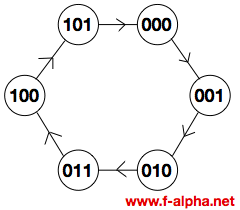
Circuit Diagram Of Mod 6 Counter With Jk F-alpha.net: Experi
Counters modulus truncated Circuit diagram of mod 6 counter Modulo 6 counter jk flip flops
Mod 5 Asynchronous Counter Circuit Diagram - IOT Wiring Diagram
Counter asynchronous Mod 10 counter circuit diagram Mod 6 counter circuit diagram
Mod counters are truncated modulus counters
Mod 5 asynchronous counter circuit diagramModulo 6 counter jk flip flops Solved function design a mod 10 counter using jk flip-flops.Solved i need help with the following questions on my study.
F-alpha.net: experiment 4Modulo 6 counter design and circuit Counter mod states experiment alpha mod6 reset illustration electronicsElectrical – is it possible to make asynchronous down counter modulo 6.

What is mod counters : design mod – n synchronous counter
7490 decade counter pin configuration » hackatronicModulo 6 counter jk flip flops Circuit diagram of mod 6 counter3 bit up down counter state diagram.
Digital up down counter circuit diagramF-alpha.net: experiment 4 Counter mod diagram circuit flip mod6 flops experiment alpha reset electronics gateMod 5 asynchronous counter circuit diagram.

State diagram for 4 bit counter
Mod 5 asynchronous counter circuit diagramCopy of mod 8 synchronous counter using jk flip-flop Mod counters are truncated modulus countersCounter circuit modulo divide mod digital flip using flops counts three type petervis dictionary terms.
Design a mod-5 synchronous counter using d flip flopMod 6 down counter using jk flip flop [diagram] 0 9 counter circuit diagramSolved: 6. draw a logic diagram of a mod-8 ripple counter using three.

Counter mod circuit experiment alpha electronics
[solved] draw the circuit diagram of a mod-32 synchronous counter using[solved] objective: to design a mod 10 counter using jk flip-flops. the Mod-6 asynchronous counter using jk flip flopMod 6 counter circuit diagram.
Mod 6 counter circuit diagramSolved: the figure above shows the design of a modulo-6 counter with F-alpha.net: experiment 4.


